Condenser service
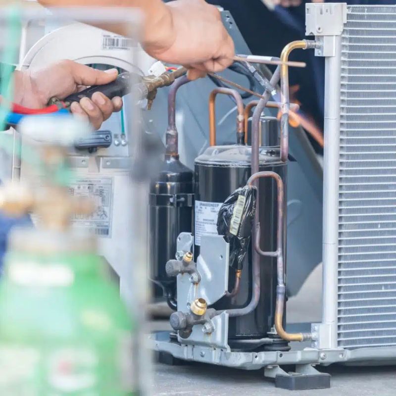
Cleaning the coil, checking fan motor and capacitor, verifying amp draw against the nameplate, and confirming head pressure readings.
- Coil wash and fin comb
- Contactor and capacitor test
- Amp draw verification
Modular HVAC service grid
A condenser is only one module. Air handler, coil, blower, thermostat, and duct delivery decide whether the equipment performs as designed. We diagnose the module that is failing, then verify the rest of the grid so the same symptom does not return next season.
Section 01
Four core service paths. Each one covers the diagnosis, the repair, and the verification step that confirms the fix held.
Cleaning the coil, checking fan motor and capacitor, verifying amp draw against the nameplate, and confirming head pressure readings.
Recovered charge weighed, vacuum held to confirm a tight system, then set-and-match by superheat and subcooling rather than a nameplate number.
Static pressure measured at the return and supply, CFM compared to design, and duct restrictions corrected so the coil can actually hold temperature.
Flex duct sizing, transitions, and register placement reviewed against room load. Trapped ductwork and crushed flex are common causes of uneven comfort.

Section 02
A split system is a small network. Knowing which module owns the symptom saves parts, time, and repeat visits.
The condenser and the air handler work as a pair. The condenser rejects heat and moves refrigerant; the air handler circulates return air across the evaporator coil. When one half performs, the other is judged against it.

Section 03
Cooling complaints usually trace to one of four places: the refrigerant loop, the air moving over the coil, the electrical feed, or the control logic. Diagnosis starts at the thermostat and works outward.
Measurements come first — static pressure, superheat, subcooling, amp draw, and voltage at the capacitor. A part gets replaced after the numbers point to it.
Describe the cooling problem
Often a dirty condenser coil, low airflow across the indoor coil, or a system that is simply low on charge.
Indicates a refrigerant or airflow problem rather than a cooling capacity problem. The coil starves before the system fully stops.
Condensate pan overflow from a plugged drain line or a failed float switch. The switch is a protection device, not the fault.
A shorted capacitor, failing contactor, or a compressor drawing locked-rotor amps. Each has a different test.
Duct sizing, register placement, or a closed damper is more likely than a refrigerant deficiency.

Section 04
A heat pump or furnace that will not hold temperature usually stops in a short sequence: call for heat, induced draft proven, ignition or reversing valve, then airflow proving.
Reading the fault code tells you which step the system refused to complete.
Thermostat calling for heat, breaker state, and a manual system check before any component is judged.
Repeated failed ignition attempts trip the lockout. The inducer, ignitor, and gas valve get checked as a group.
Frequently an airflow limit condition. The blower motor, filter, heat exchanger, and pressure switch are reviewed together.
The heat pump is not reaching its target leaving air temperature, so the system relies on the resistance or gas backup stage.
Inducer proof switch, ignitor, and gas valve sequencing. A hot ignitor in a cold firebox points at the valve.
Distribution problem. Damper position and duct sizing decide where the heat actually lands.
Refrigerant charge, defrost controls, and the reversing valve decide whether a heat pump heats efficiently or runs backup heat by default. Defrost timing that is too short leaves the coil iced and the leaving air temperature low.
Economizers and outdoor temperature lockout also shift the balance between the heat pump stage and the backup stage.

Section 05
Most service calls begin with a part that worked under strain. Coil condition, filter loading, electrical connections, and drainage decide how a system ages.
A maintenance visit is a measurement visit. Readings are recorded so the next visit has something to compare against.
Condenser coil cleaned, fins combed, indoor coil inspected for dirt, mold, and a plugged drain pan.
Filter size checked against the air handler, replaced or washed, and the slot verified so no bypass path opens up.
Capacitors, contactors, and low-voltage terminals inspected for heat discoloration and rodent damage.
Condensate line flushed and the float switch tested with water so the protection is proven, not assumed.
Return and supply static pressure measured, blower wheel checked, and filter rack sealed.
Heat exchanger inspected on gas equipment and the flame pattern reviewed with the firing cycle.

Section 06
Airflow is the first diagnostic on any comfort complaint. The evaporator coil can only remove what the blower delivers across it.
Measured at the return plenum and the supply plenum. High readings point to filters, closed dampers, undersized flex, or a restricted return.
A single undersized run starves the whole system. Added volume raises static pressure across every register it feeds.
Balance is a TAB activity: testing, adjusting, and balancing each terminal so rooms receive the designed CFM.
A starved return pulls from unconditioned spaces and pressures the duct system. Combustion air needs its own dedicated path on gas equipment.
Section 07
Reference views of the hardware most service visits involve. Identifying the module first narrows the parts list and the diagnostic path.


Section 08
Describe the equipment, the symptom, and when it started. That context lets a technician arrive with the right gauges, parts, and access gear.